Z80 bits
... returning to 80's computing
Troubleshooting Guide, continued.
If you have a logic analyser, even a cheap one, you can use following charts and compare if your kit function properly. When you turn on your retro computer you will see a special pattern of activity on the bus. After you hit reset this pattern will change, and this may change again if you boot into BASIC or CP/M. The pictures below were made with my NeoClassic setup.
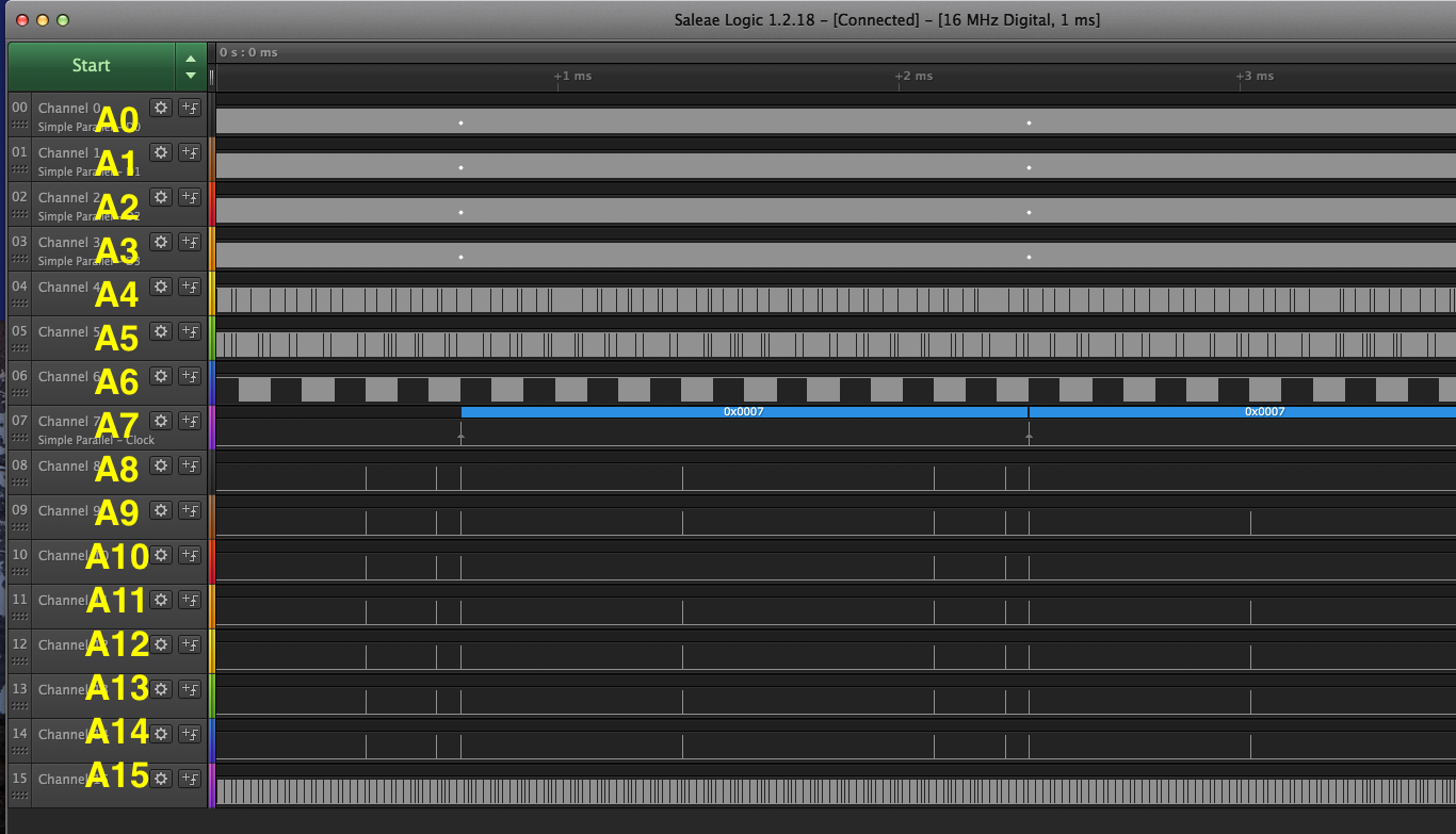
The address lines (A0 to A15) after powering up the kit. I looks like its running through all addresses.
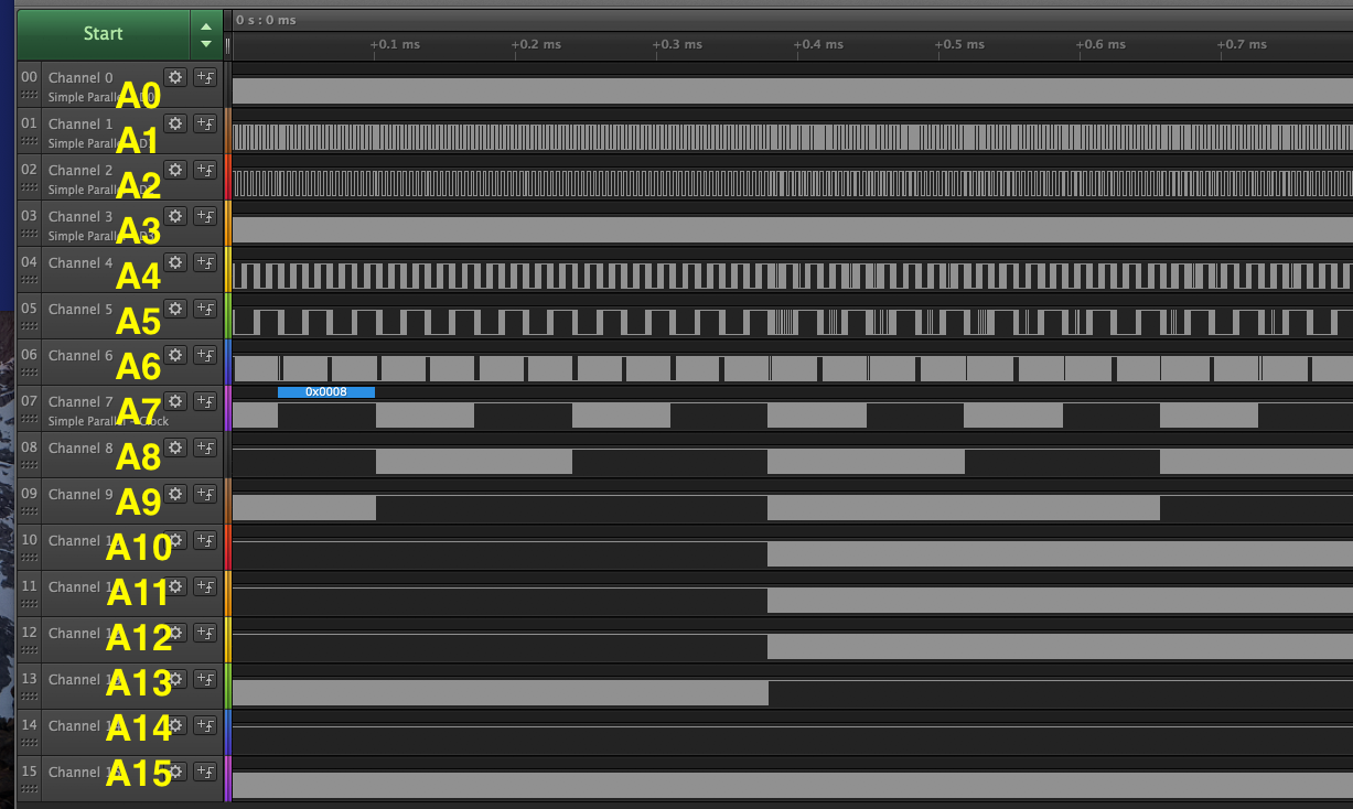
After booting into 32kb BASIC, the activity is limited to a more narrow address space.
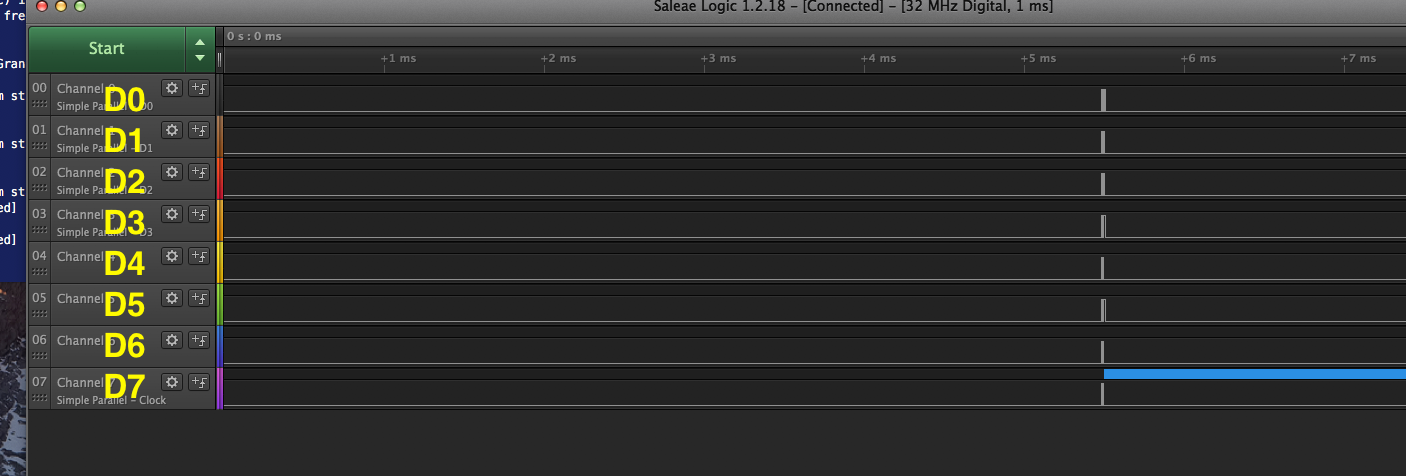
The data lines (D0..D7) after power on. There is very little activity.
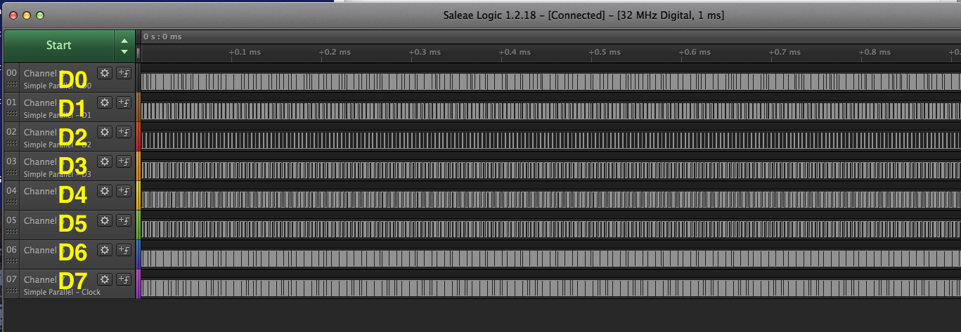
After reset there and the system is running the bootloader we observe acticity on all data lines.
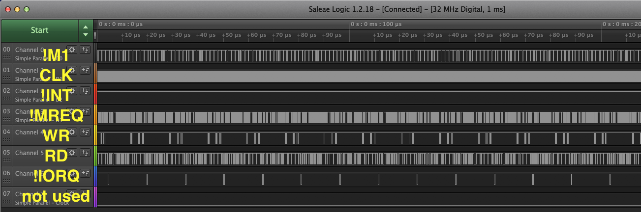
The control signals after powerup. There are activity in many of the lines. Clock, !M1, !MREQ, !IORQ, !RD and !WR, but not in the interupt signal !INT. Most of these signals are active low, meaning they are high when they are off.
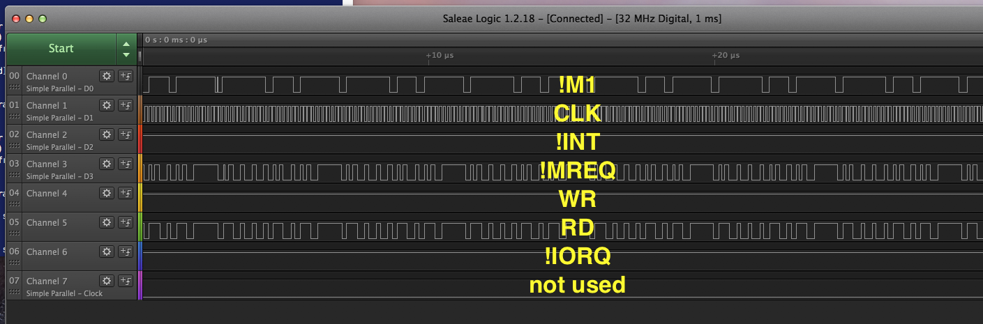
The control signals after reset. No big change.
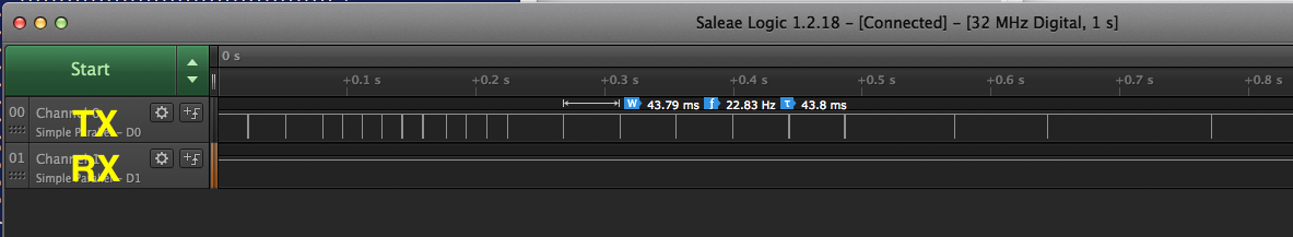
The TX and RX lines; here running the fractal program in BASIC.