Z80 bits
... returning to 80's computing
Troubleshooting backplane the easy way.
1. Do a visual inspection from above and from an angle. A good magnifying glass is very helpful.
Look for solder bridges, weak solder joints or missing solder joints.
Do a clean-up and wash with isopropyl alcohol and a toothbrush, to remove flux residues.
2. Check for short circuit between Vcc (+5V) and ground (GND).
This is easiest performed by using a multimeter in continuity mode.
3. Add power (+5V) to the backplane, if it doesn’t smoke you can continue.
4. Check the voltage between Vcc and GND with a multimeter, if it is close to +5V it’s okay.
If not, that’s a sign of a bad power source or leakage in the system.
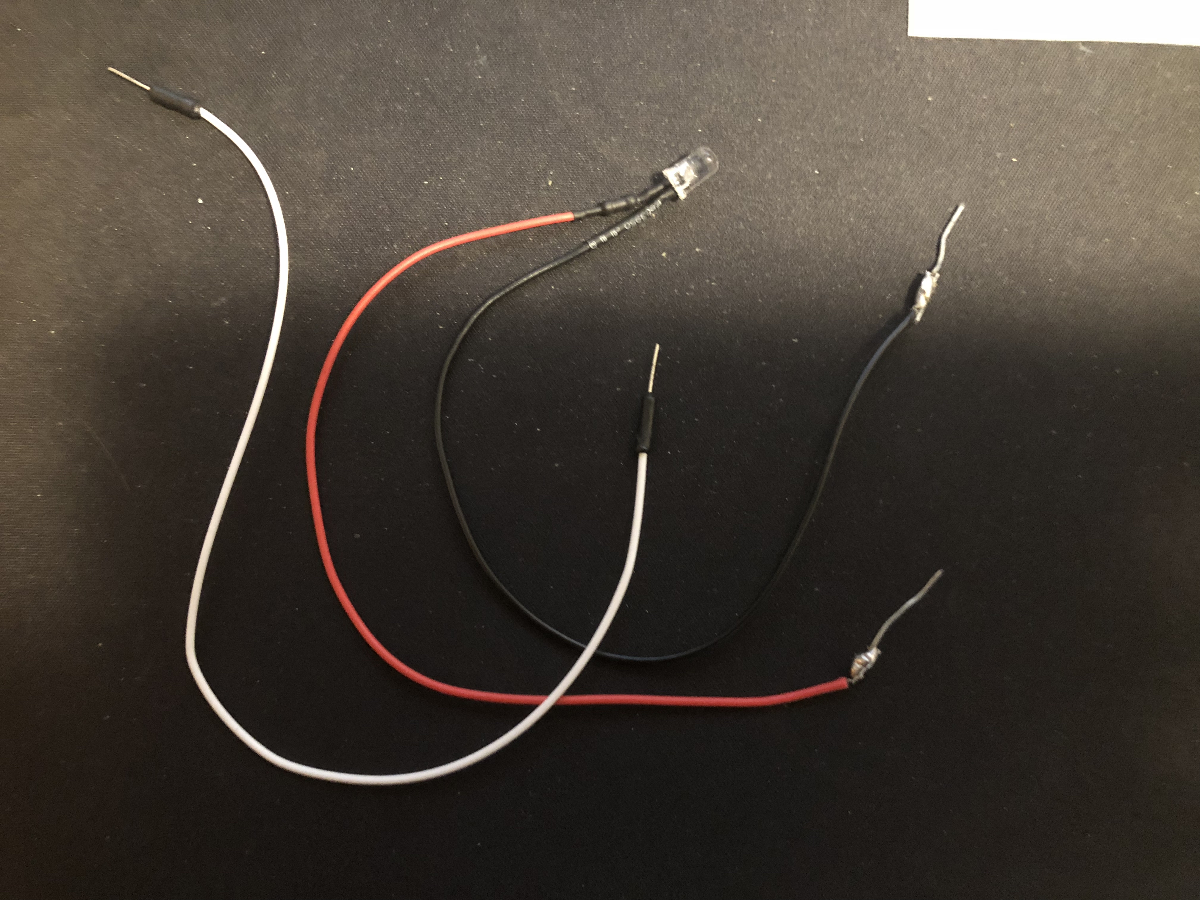
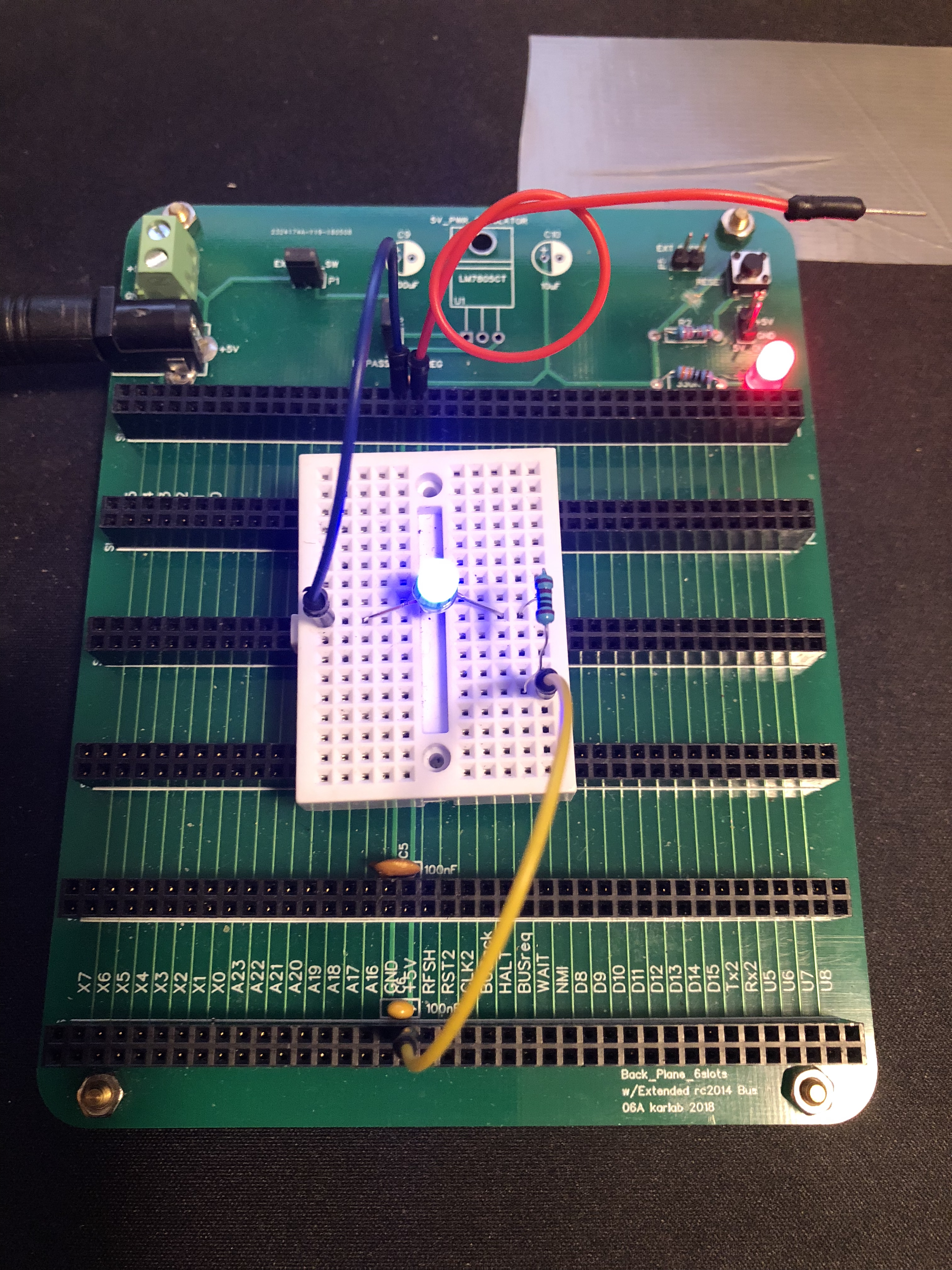
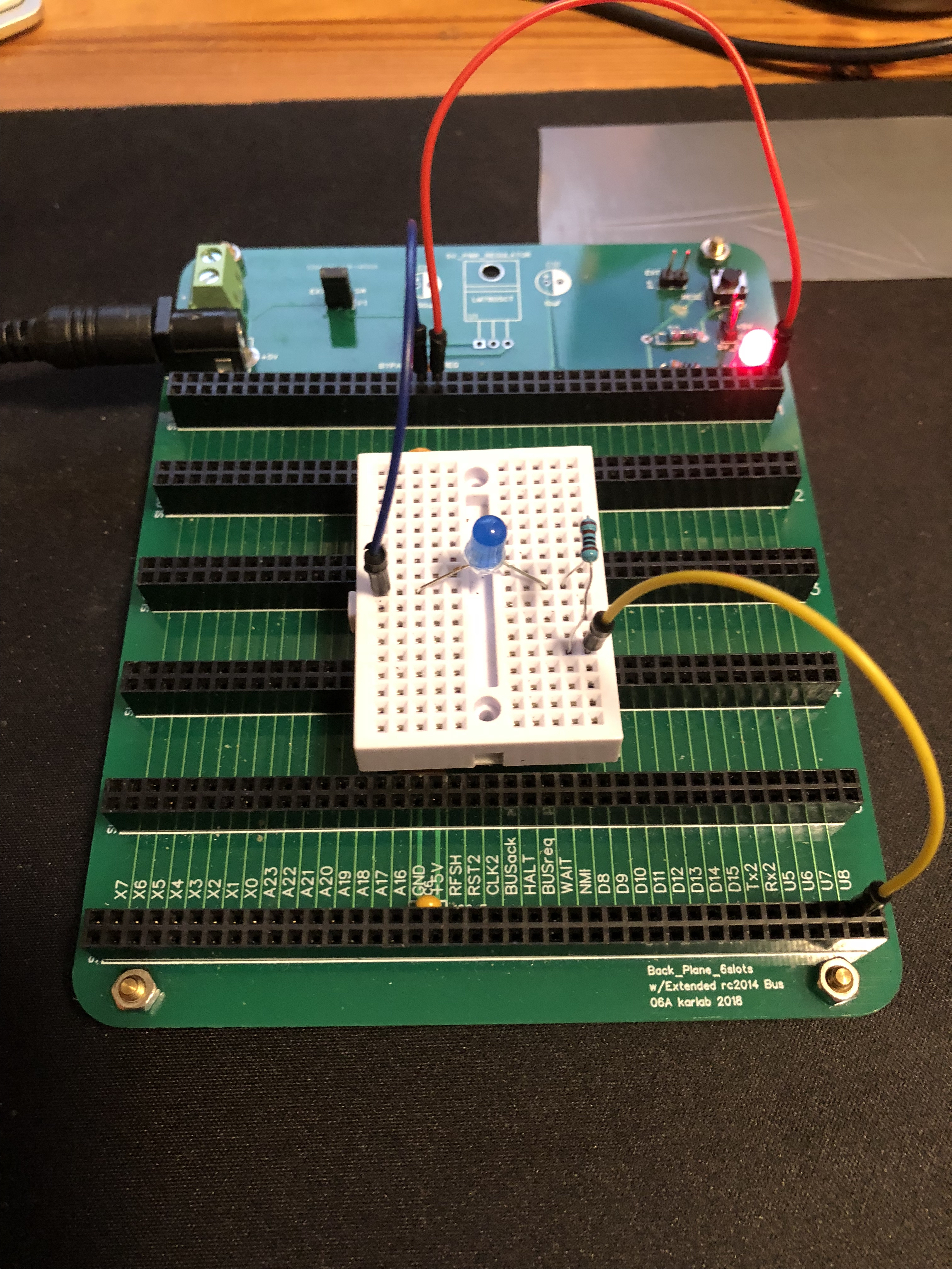
5. Build yourself a little test-rig consisting of a small breadboard, few patching wires, a resistor (e.g., 1K, this is not critical, to protect the led from not burning up), and a led (remember polarity). See picture 1 below: black/blue wire = GND, red wire = +5V, yellow wire = probe.
6. While there is power to the backplane, connect the test rig to Vcc/+5V and GND.
The led should light up, if not check the test rig and test the voltage between Vcc and GND again.
7. So far so good. Keep the test-rig connected to GND (blue/black wire) during the whole process.
8. Testing one line at the time: Start testing by connecting the red wire to the pin/line (e.g., pin 1/A15 in slot 1) you want to check (Picture 2). With the probe (yellow wire) you connect to the same line (pin 1/A15) in a different slot (e.g., slot 2), if it lights you have a connection and if not, there is a bad connection. Keep testing for all the lines in the different slots (slots 2 - n).
9. Testing for short circuit: Continue testing, but this time you test the neighboring lines (Picture 2, Right). If all is good, you will not see any light, if it lights up you got a short circuit.
You only have to this test on one slot and don’t test for lines which are further away, just the next neighbor line.
10. Some lines may act differently, like those that are active low (passive high), e.g., the reset line. The reset line can be tested by keeping the red wire not connected and the probe (yellow wire) to the reset line. The led should light up. Then press the reset button, the light should turn off.
Picture 1. The power and Rig works OK.
Black/blue wire = GND
Red wire = +5V (not connected in picture)
Yellow wire = probe (connected to +5V)
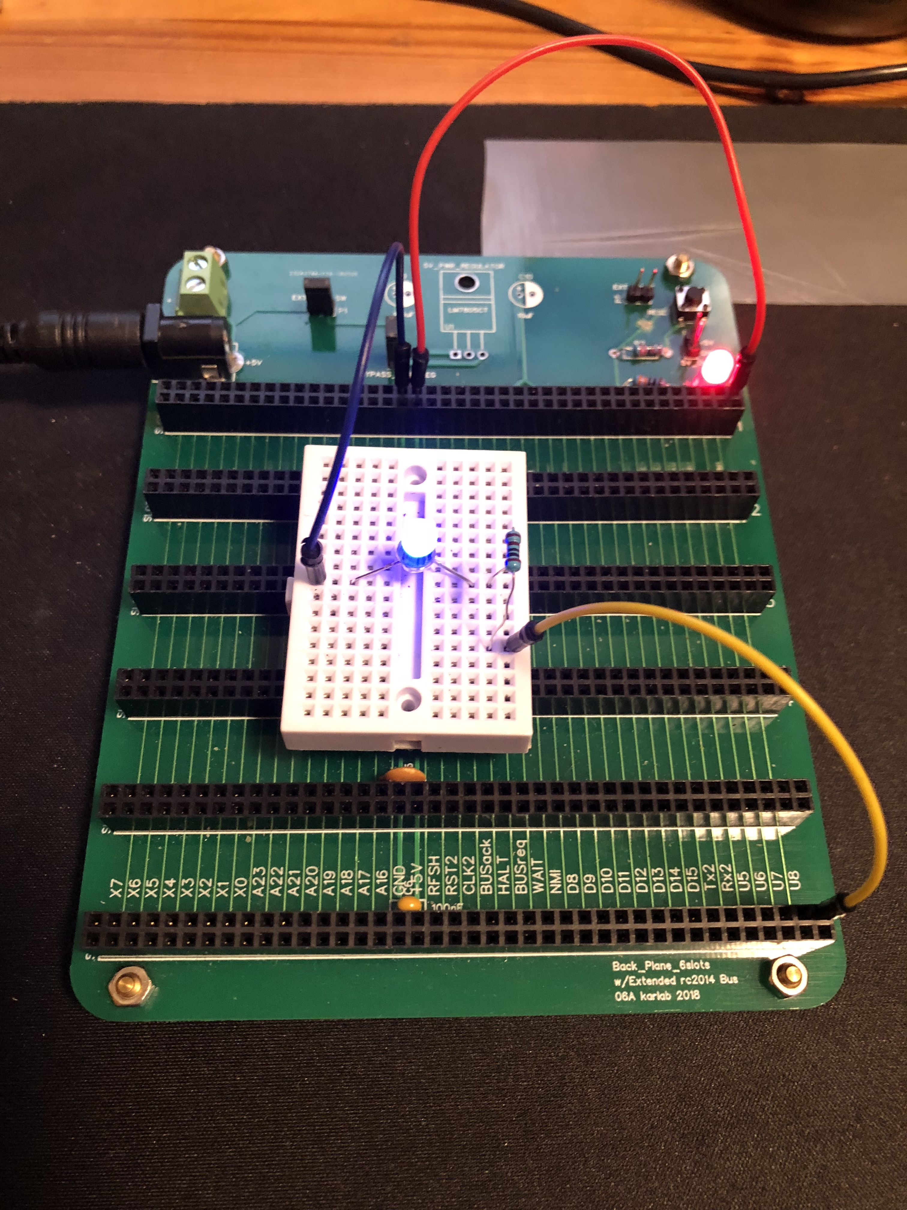
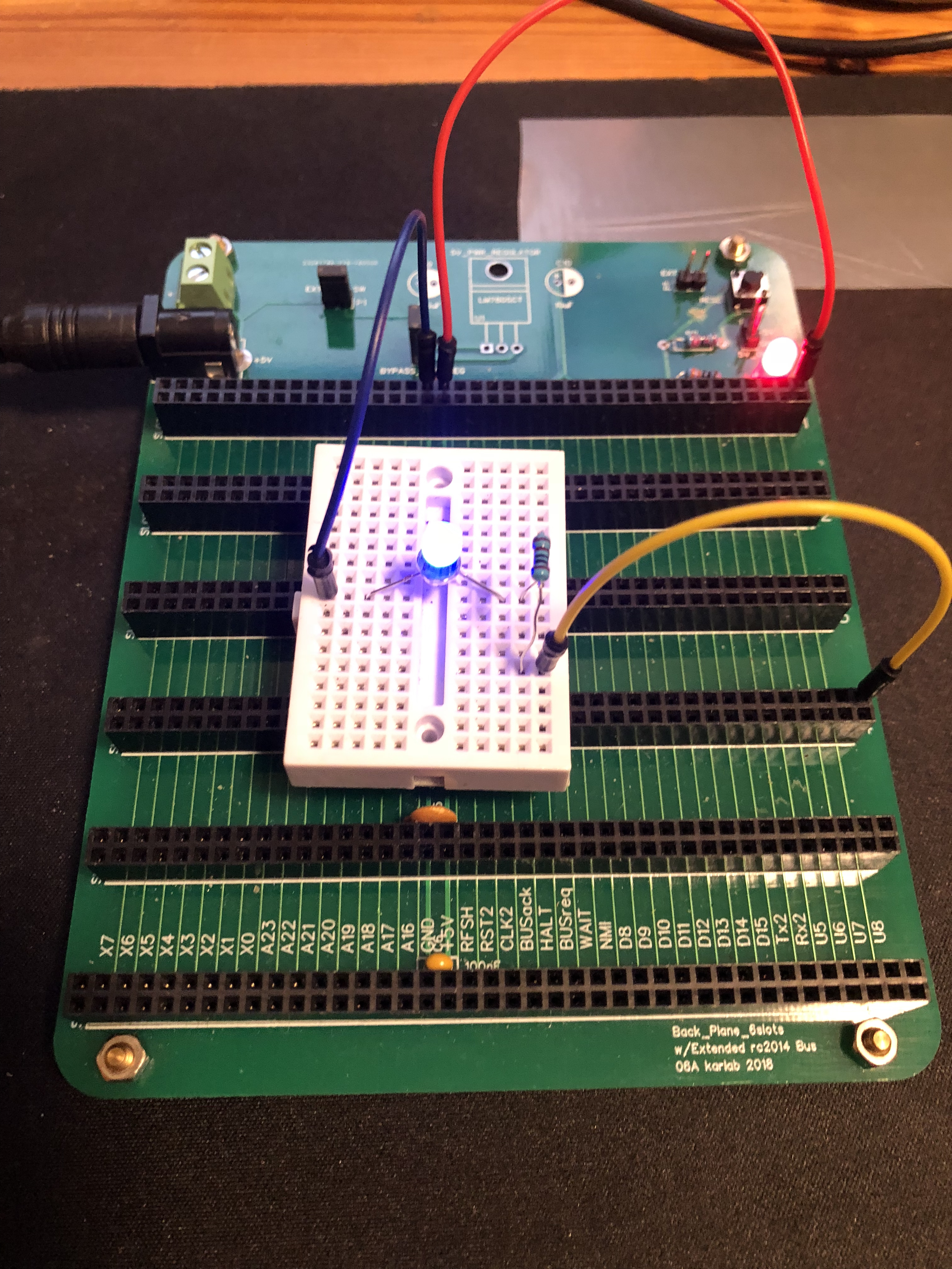
Picture 2. Black/blue wire connected to GND. Red wire connects +5V to connector 40 (leftmost) in slot 1 (furthest away). LEFT: Yellow is probing connector 40 in slot 6 (= light = OK). MIDDLE: yellow is probing connector 40 in slot 4 (= light = OK). RIGHT: Yellow is probing connector 39, slot 6 (= no light = no short circuit).
TIP: here is a simple tool I have made testing for continuity. If you are like me, being annoyed by the beeps from the multimeter, this is the solution and it is also faster to use. The black wire is connected to ground, the red wire is used as probe, and the white wire is to connect +5V and line to be tested.